Warning
You are reading an old version of this documentation. If you want up-to-date information, please have a look at 1.1 .Example - Rockwell Studio 5000 Logix Designer ®
This section gives an example of a simple integration of EYE+ XTD with the EtherNet/IP module in Rockwell Studio 5000 Logix Designer ® version 31.00.00.
Prerequisites
- Before you start, please make sure you have downloaded the following files:
EYE+ XTD EtherNet/IP EDS file (Electronic datasheet)
Studio 5000 Logix Designer ® sample code
These files can be downloaded from EtherNet/IP Downloads.
Once you have downloaded the necessary files, launch the EDS Hardware Installation Tool.
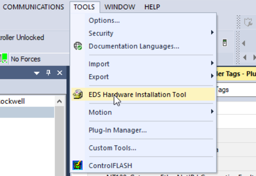
Fig. 208 Launch EDS Hardware Installation Tool
The Rockwell Automation’s EDS Wizard opens. Click on “Next”.
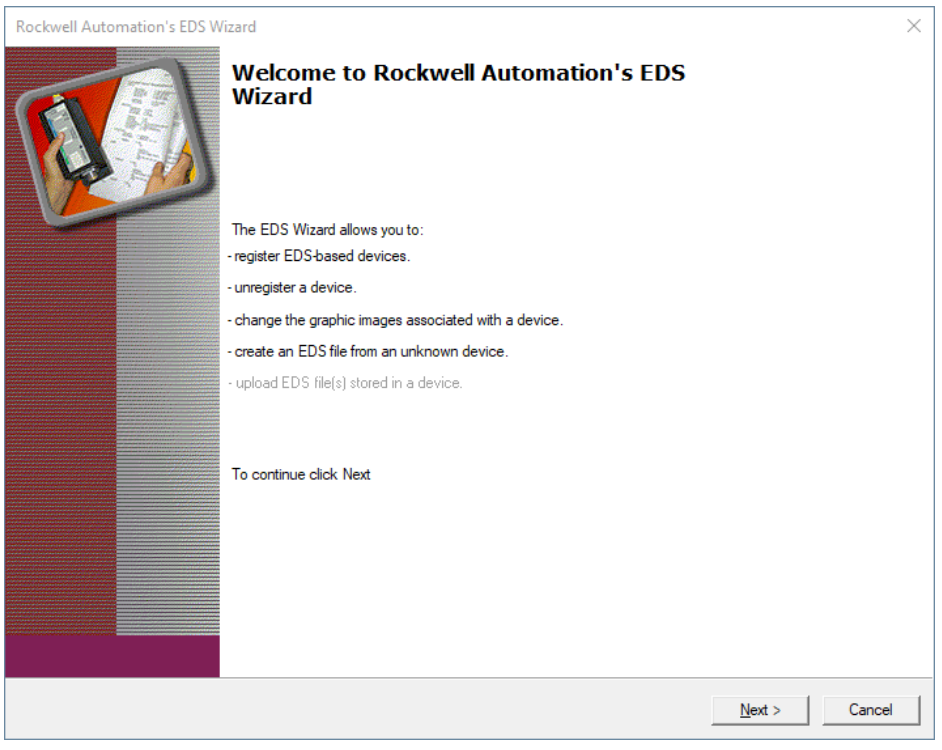
Fig. 209 Rockwell Automation’s EDS Wizard
Select “Register an EDS file” and click on “Next”.
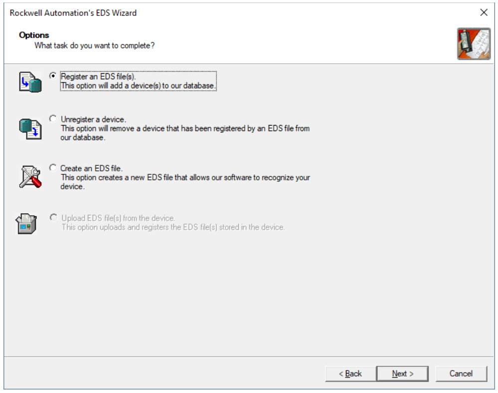
Fig. 210 Register an EDS file
Select the EYE+ XTD EDS file you downloaded from EtherNet/IP Downloads.
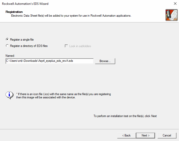
Fig. 211 Register EYE+ XTD EDS
Click on “Next” 4 times to finalize the EYE+ XTD EDS registration.
Basic integration
Once the EYE+ XTD EDS is registered, add a new EYE+ XTD module to your I/O Configuration by right-clicking on your Ethernet board.
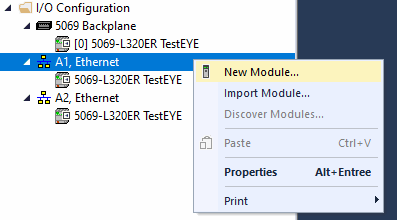
Fig. 212 Add a new module
Select EYE+ XTD and press “Create”.
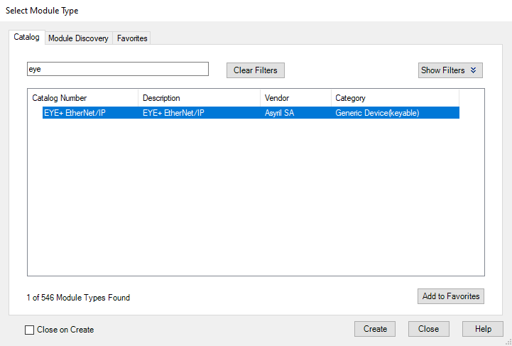
Fig. 213 Create EYE+ XTD EtherNet/IP module
In order for our Logix 5000 sample code to work out of the box, set the module name to EyePlus. Configure the IP settings. The default IP Address of the EYE+ XTD Ethernet/IP module is 192.168.210.10. If you would like to change this address, please refer to the Module configuration section.
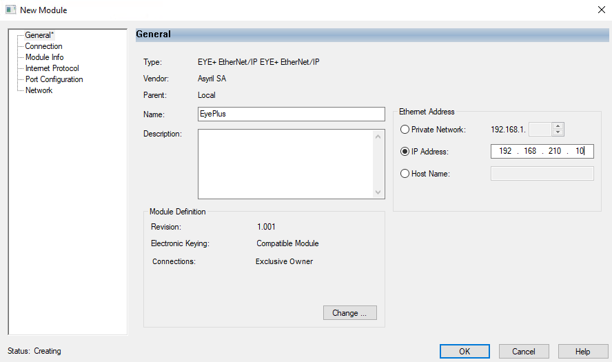
Fig. 214 Configure Name and IP Address
You should now see the EYE+ XTD IOs in your controller tags. When you go online, the tag EyePlus:I.System_State should
be 128, corresponding to the Ready state.
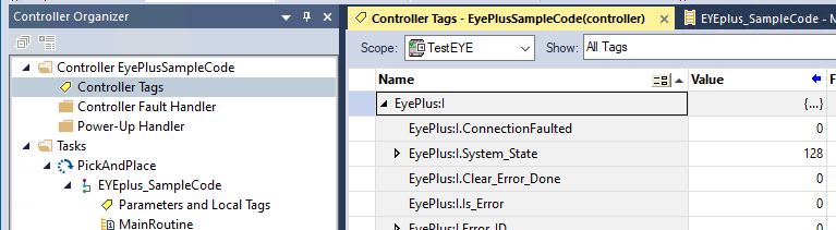
Fig. 215 EYE+ XTD tags
Create a new task, select it and import a component.
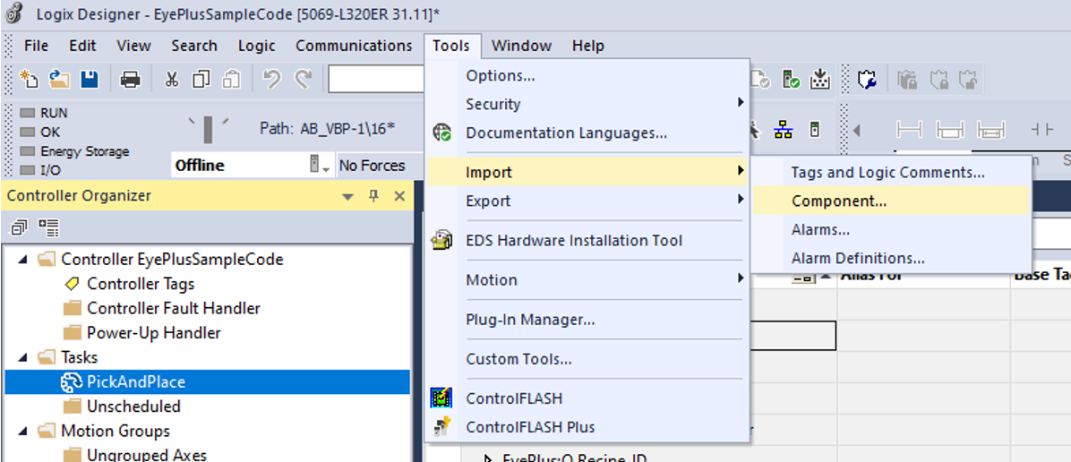
Fig. 216 Import a component
Choose the Logix sample code.
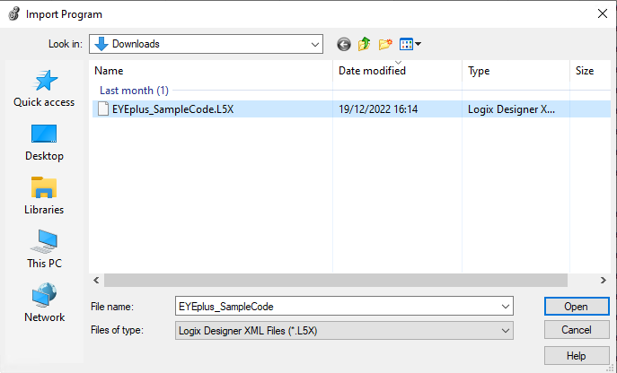
Fig. 217 Open Logix 5000 sample code
Validate the import configuration by clicking OK.
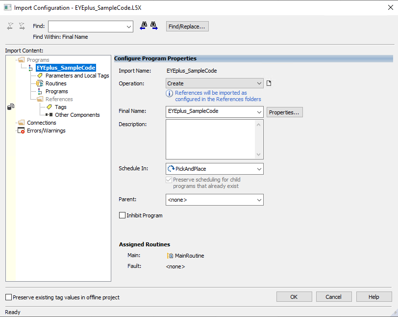
Fig. 218 Import Configuration
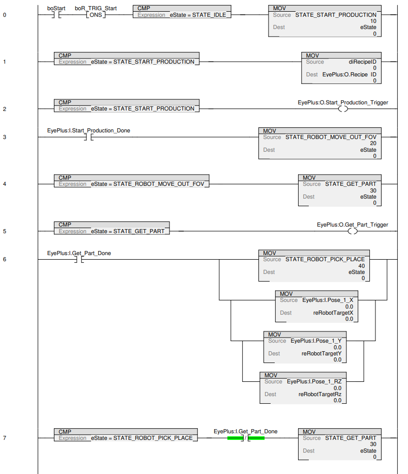
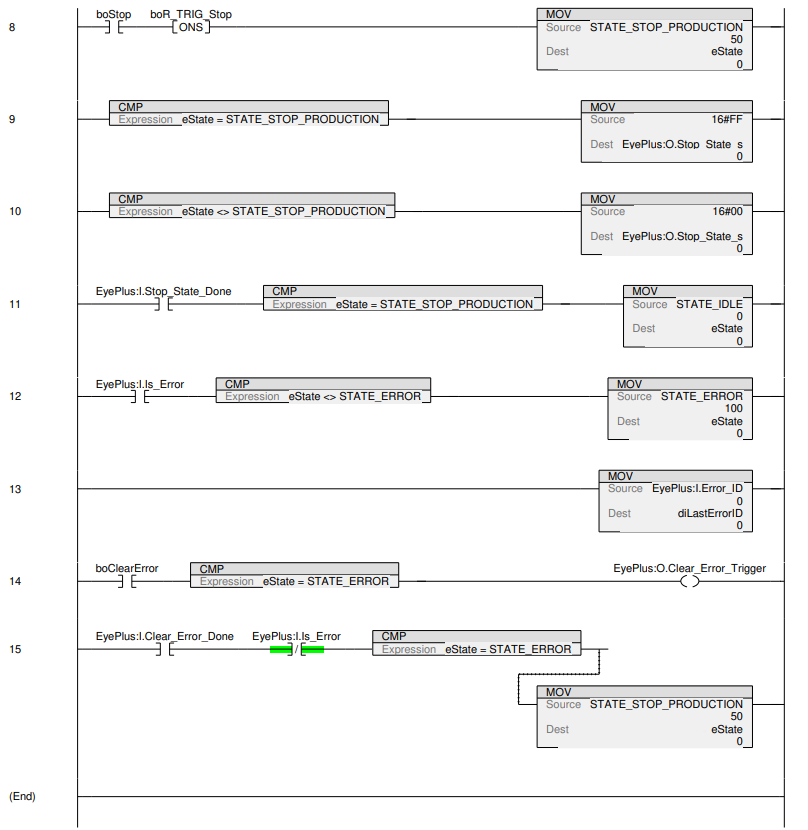
The following ladder diagram should now have been imported in your task. You can start the production of a recipe that
was previously created on your EYE+ XTD controller by setting udRecipeID to the ID of that recipe, then setting
boStart to True. The coordinates of the part found will be returned in reRobotTargetX, reRobotTargetY and
reRobotTargetRz.