Warning
You are reading an old version of this documentation. If you want up-to-date information, please have a look at 1.1 .First startup
This chapter guides you from unpacking your elements to getting your first connection to EYE+ XTD Studio.
Mounting the EYE+ XTD Controller
Unpack the EYE+ XTD Controller.
Fix the EYE+ XTD Controller inside your electrical cabinet using four M4 screws. We advise you to fix the EYE+ XTD Controller vertically and to ventilate the cabinet. See EYE+ XTD Controller standard specifications section for more details.
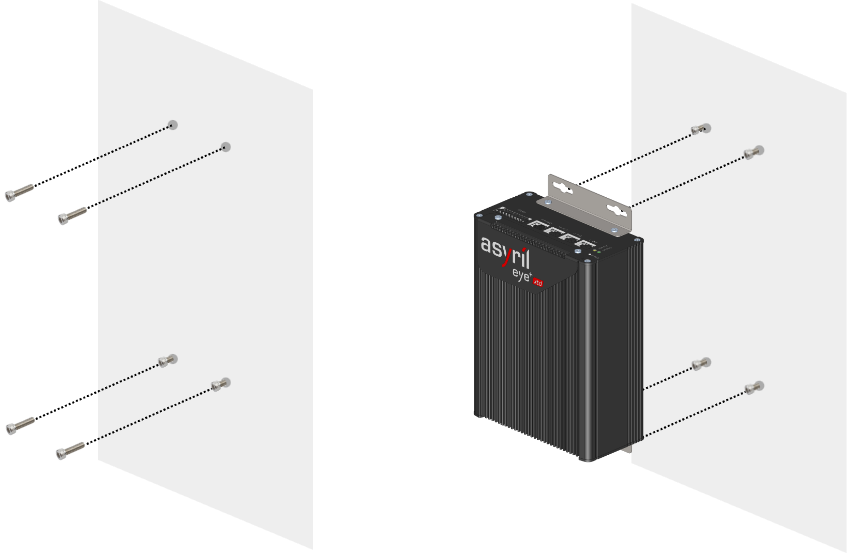
Fig. 5 EYE+ XTD Controller mounting step 1 and 2
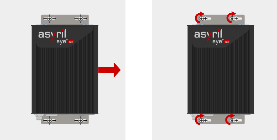
Fig. 6 EYE+ XTD Controller mounting step 3 and 4
Tip
EYE+ XTD Controller dimensions are presented in the EYE+ XTD Controller section.
Mounting the camera
Unpack the camera and the lens. The lens is already mounted on the camera.
Fix the camera using the four M3 mounting holes (labeled M on Fig. 24).
Camera positioning:
Camera must be placed orthogonal to the picking area and above its center.
Important
Orthogonality between the camera and the picking area is essential for accurate part detection. The camera must not be tilted relative to the picking area. Exercise particular care during this installation step.
Distance between the front face of the lens and the picking area has to correspond to the working distance.
Ensure the field of view is correctly oriented. The EYE+ XTD logo on the camera should be parallel to the shorter edge of the picking area. For an illustration, see Fig. 7.
Important
We recommend you design the camera mounting so that it can be adjusted in x, y and z. Make sure that the camera position can be adjusted mechanically with a tolerance of -10mm/+30mm in z and -10mm/10mm in x and y.
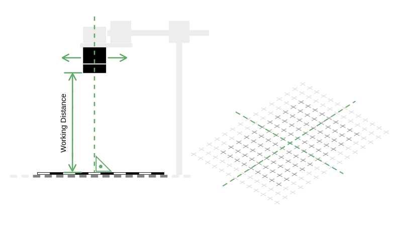
Fig. 7 Camera positioning
Tip
Camera and lens dimensions are presented in section Camera and lens.
Cable connection
Connect the M12 Ethernet connector of the camera to the Camera port of the EYE+ XTD Controller port with an Ethernet cable (PoE Cat6 S/FTP).
Connect the RJ45 port of your computer to the Communication port of the EYE+ XTD Controller with an Ethernet cable (at least Cat5e SF/UTP).
Connect the provided power cable on the EYE+ XTD Controller to a 24V DC (6.5A) power supply (see Table 12 for wiring).
(Optional) Connect your robot or PLC to the Communication port of the EYE+ XTD Controller with an Ethernet cable (at least Cat5e SF/UTP). It is not necessary to connect your PLC or robot to complete the Quick Start. You can connect it later.
Note
To communicate via TCP/IP while simultaneously accessing EYE+ XTD Studio, you must add an unmanaged Ethernet switch or utilize the External 1 or 2 Ethernet ports.
(Optional) Connect the frontlight to the Frontlight input of the EYE+ XTD Controller with the provided cable.
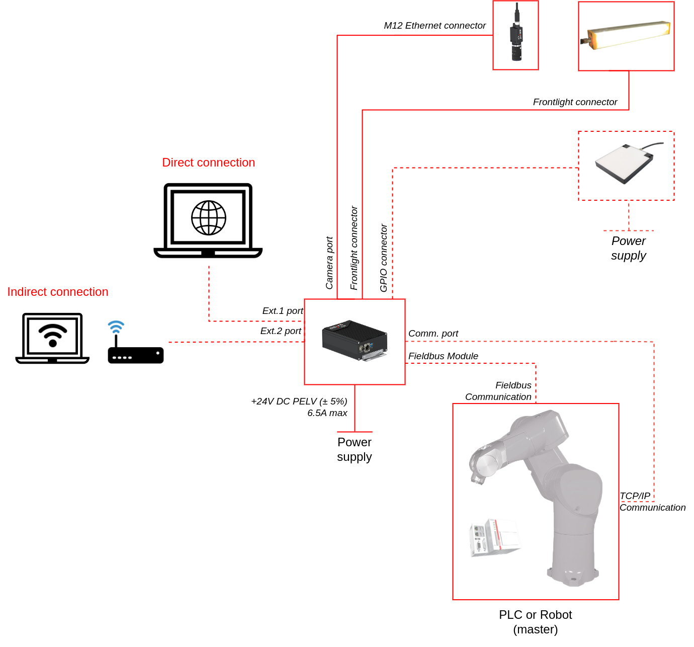
Fig. 8 EYE+ XTD wiring diagram
Your first connection
Once the three previous steps are finished, you should be able to access EYE+ XTD Studio from your personal computer.
Change the IP address of your computer to be on the same network as the EYE+ XTD Controller (Table 4).
EYE+ XTD Ethernet port |
Default IP address |
Default subnet mask |
|---|---|---|
Communication |
192.168.1.50 |
255.255.255.0 |
Open your web browser (see Recommended web browsers) and enter in the address bar: 192.168.1.50. Alternatively, you can use EYE+ XTD Locator to automatically detect your EYE+ XTD, please refer to EYE+ XTD Locator.
If everything is correct, the EYE+ XTD Studio HOME page (Fig. 9) will appear.
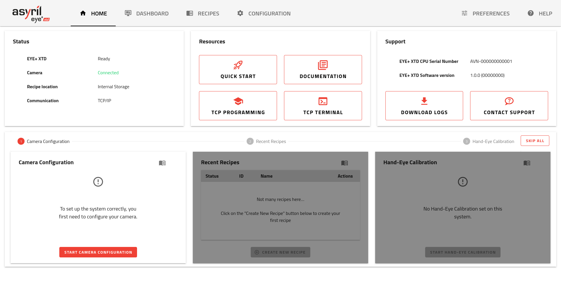
Fig. 9 EYE+ XTD Studio HOME page
Tip
If this interface does not appear, please check the cable connection and verify that the IP address of your PC is on the same network as the EYE+ XTD Controller, for example 192.168.1.55.
If the issue persists, refer to Connection lost? for troubleshooting guide.
The page is the first page you see when accessing EYE+ XTD Studio (Fig. 9). The page is separated in two different areas.
The upper area displays system status, useful resources and support information. The lower area is used as an onboarding tool that will guide you through the initial commissioning. It contains the following steps:
Let’s start with Camera configuration.