Warning
You are reading an old version of this documentation. If you want up-to-date information, please have a look at 1.1 .How to create a pattern for the camera calibration?
The calibration pattern (i.e., the chessboard) serves as the foundation for accurate vision system calibration. Using a high-quality, properly prepared pattern is essential for achieving precise calibration results. Poor calibration can negatively impact the entire vision pipeline, leading to lower part detection rates, reduced pick point accuracy, and overall decreased system performance. Please refer to the chapter What performs vision calibration?, to understand the theory behind the vision calibration and why it is important.
EYE+ XTD can be used with standard calibration patterns; however, for optimal performance, a custom pattern is recommended. When designing and using a custom pattern, the following guidelines should be followed to ensure the best calibration results:
Pattern Size: The pattern should closely match the dimensions of the picking area to maximize calibration accuracy within the region of interest.
Square Count: The number of squares should be sufficient to provide enough reference points for accurate correction, while avoiding excessive density, which can hinder reliable detection. Typical size for a pattern is 20 by 14 squares.
Flatness: The pattern must be as flat as possible. It should be printed on high-quality material and ideally mounted on a rigid, non-deformable surface to prevent warping during use.
Radon checkers: Rounded squares on the edges to help detecting the full pattern.
How to Generate the Pattern
Before generating the calibration pattern, ensure you have the following information:
The dimensions of the picking area (width and height) in millimeters.
We recommend using the calib.io pattern generator to create your custom checkerboard:
Open the link to calib.io pattern generator.
Set the Target Type to
Checkerboard.Enter 14 for
Rowsand 20 forColumns.Specify the following:
Board width: equal to the picking area width (in mm)
Board height: equal to the picking area height (in mm)
Checker width: approximately
\[\text{Checker width} \approx \frac{\text{Picking area width}}{20}\]
Enable the
Finder Markeroption to help you center the camera to the center of the picking area.Enable the
Radon Checkersoption to improve detection robustness.
The generated pattern should closely match your picking area and resemble the example shown below.
You can save the pattern by clicking “Save pattern as PDF”.
The resulting pattern should resemble the illustration below: a high-contrast checkerboard grid with evenly spaced squares, covering the specified picking area dimensions. This layout ensures optimal corner detection and accurate calibration results.
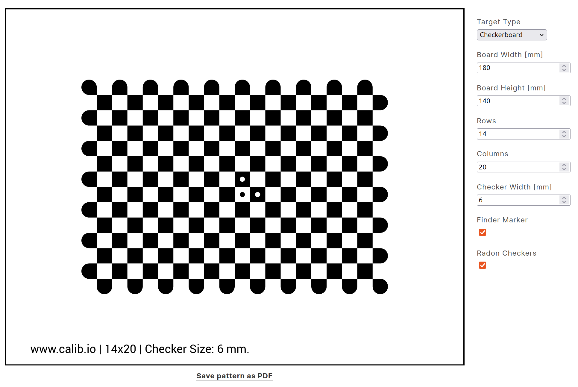
Fig. 235 Example of a calibration pattern generated by calib.io.
Before using the calibration pattern, it must be printed at full scale. Ensure that the printout accurately reflects the specified dimensions, this is critical for achieving reliable calibration results. The pattern should be printed on high-quality paper and mounted on a flat, rigid surface to prevent warping or bending during use. Also, verify that no scaling has been applied during printing (set the print scale to 100%) and measure the printed pattern to confirm it matches the intended size.