Warning
You are reading an old version of this documentation. If you want up-to-date information, please have a look at 1.1 .GPIO
Pinout
The following illustration shows the pinout of the male GPIO connector present on the EYE+ XTD Controller.
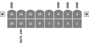
Fig. 35 GPIO pinout of the male connector, viewed from the side of the EYE+ XTD Controller
The labeled pins have a dedicated usage attached to them which sometimes requires a specific configuration in EYE+ XTD. The usage of the currently supported pins is described in Table 18.
Pin |
Designation |
Usage |
|---|---|---|
1 |
+24VDC_GPIO |
Reserved for 24V output. Do not use! |
3 |
+12VDC_GPIO |
Reserved for 12V output. Do not use! |
5 |
+5VDC_GPIO |
Reserved for 5V output. Do not use! |
13 |
OUT1_24V |
Trigger for external lighting |
Important
The unlabeled pins (7, 8, 9, 10, 11, 12, 14 and 15) are reserved for future use and must be left unconnected. Failure to comply with this instruction may result in permanent damage to the EYE+ XTD Controller or to your own device.
Power specifications
Table 19 summarizes the EYE+ XTD Controller power specifications for the GPIO connector.
Pin |
Designation |
Max current |
|---|---|---|
13 |
OUT1_24V |
500mA |
Important
Never attempt to draw more power from the outputs than specified in Table 19. This might result in permanent damage to the EYE+ XTD Controller.
Note
The OUT1_24V output should only be used to trigger an external light. It is not designed to supply power to an external lighting system.
For example, it can be used to activate a relay or control input on an external lighting controller. This approach ensures correct lighting behavior and prevents possible damage to the EYE+ XTD Controller.