Warning
You are reading an old version of this documentation. If you want up-to-date information, please have a look at 1.1 .Ethernet Connections
General Ethernet Settings
Four Ethernet connectors are available on the EYE+ XTD Controller.
Ethernet port |
Device connected |
IP address |
Subnet mask |
|---|---|---|---|
Communication [2] |
Robot, PLC, computer |
192.168.1.50 |
255.255.255.0 |
External 1 |
Robot, PLC, computer |
192.168.10.50 |
255.255.255.0 |
External 2 |
Robot, PLC, computer |
192.168.20.50 |
255.255.255.0 |
Camera |
Camera |
192.168.21.1 |
255.255.255.0 |
Note
Refer to Communication Configuration section to change the Ethernet configuration. Note that only External 1, External 2 and Communication can be changed.
Camera
Camera connection
Connect the camera M12 Ethernet connector to the Camera PoE port of the EYE+ XTD Controller with a PoE Ethernet cable. The Ethernet cable should be at least Cat6 S/FTP. The camera LED should start flashing green after a moment.
Important
This cable is supplied by Asyril in different lengths (2m, 5m, 10m, 15m, 20m). Always use the cable supplied by Asyril to ensure good camera performance. Otherwise, it may result in communication loss with the camera.
LED behavior |
Camera status |
|---|---|
LED off |
Not powered |
Red |
Error |
Flashing red |
Powered but no Ethernet link established |
Flashing green |
Powered, Ethernet link established, but no network traffic |
Green |
Powered, Ethernet link established and there is a network traffic |
Camera specifications
The camera uses X-coded 8 position M12 connector for Ethernet communication.
The default Camera port configuration on EYE+ XTD Controller side is presented in General Ethernet Settings.
Communication
The Communication port can be used for two different actions:
Communicate with robot or PLC through TCP/IP Communication.
Access EYE+ XTD Studio to configure devices (camera, robot,…), create new recipes or to visualize the dashboard.
External 1 & External 2
The External 1 and External 2 ports are used to connect the system to external devices such as robots, PLCs, or computers. They are especially useful when:
You want to separate networks: For example, one port can connect to the factory network while the other connects to a robot or PLC. This keeps communication isolated and avoids potential conflicts.
You do not want to use a switch: These ports let you connect two devices directly to the system without needing an external network switch.
You need a clear setup: Using separate ports makes it easier to troubleshoot, monitor traffic, or assign specific roles to each connection.
Each port has its own IP address (General Ethernet Settings) and works independently from the others, so you can configure them based on your network setup.
TCP/IP communication with robot/PLC
Connect your robot or PLC to the Communication port of the EYE+ XTD Controller with an Ethernet cable. The Ethernet cable should be at least Cat5e SF/UTP. Make sure that your robot or PLC IP address is on the same network as the Communication port (see General Ethernet Settings).
If the IP address of your robot or PLC is not on the same network, you will have to change the IP address of the Communication port from EYE+ XTD Studio. Please refer to section Communication Configuration to perform this configuration.
Note
This Ethernet cable is not part of the EYE+ XTD kit but can be ordered separately.
Important
Auto-negotiation must be enabled on the robot/PLC side to ensure seamless communication and optimal performance. Using a device without auto-negotiation can lead to various network issues, including duplex mismatches, speed mismatches, connectivity problems, increased latency, and packet loss, all of which can degrade network performance and reliability.
Access EYE+ XTD Studio
Access to EYE+ XTD Studio is necessary to configure devices (camera, robot), create recipes or to visualize the dashboard. The Dashboard of EYE+ XTD Studio will display some information about the current production and is also accessible while the EYE+ XTD Controller is in production state.
The Communication port can be connected either directly to your computer or through a company network. The Ethernet cable must be at least Cat5e SF/UTP.
Note
This Ethernet cable is not part of the EYE+ XTD kit but can be ordered separately.
Note
If you want to communicate through TCP/IP and also access EYE+ XTD Studio at the same time, you will need to add an unmanaged Ethernet switch which can be ordered separately.
Also make sure to have all your devices on the same network.
Direct connection
Direct connection is a direct Ethernet connection between your computer and EYE+ XTD. To do so, connect the RJ45 port of your computer to the Communication port of the EYE+ XTD Controller using an Ethernet cable. The Communication port is set to a fixed IP address by default (General Ethernet Settings).
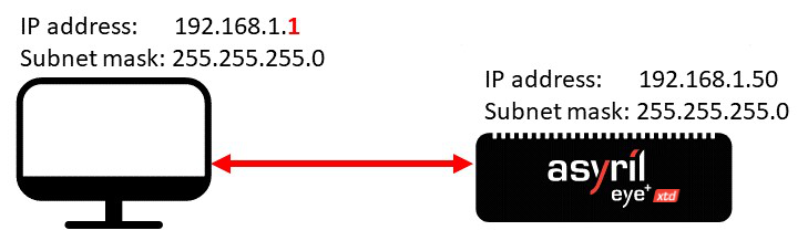
Fig. 31 Direct connection through the port Communication
Change the IPv4 configuration of your computer by choosing an IP address and subnet mask so that it is on the same network as the EYE+ XTD Controller. For example, apply the configuration presented in Table 16.
Ethernet port |
IP address |
Subnet mask |
|---|---|---|
Computer RJ45 |
192.168.1.1 |
255.255.255.0 |
Once your computer is properly configured, open your web browser and enter the IP address of the Communication port in the address bar (for example 192.168.1.50). The home page (Fig. 32) should appear.
Note
If the home page does not appear, please refer to Connection lost?.
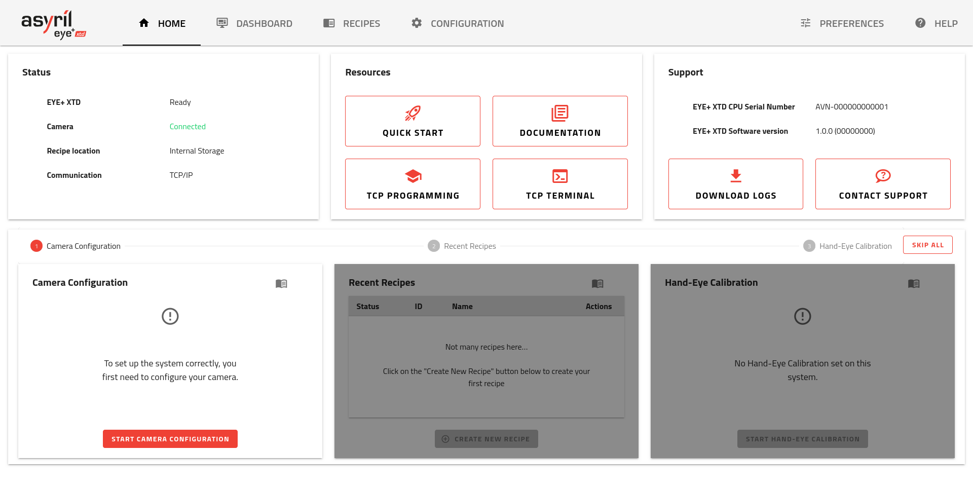
Fig. 32 EYE+ XTD Studio home page with EYE+ XTD in ready state
Note
If the home page does not have the same display as in Fig. 32, refer to the sections Recommended web browsers and Interface display.
Indirect connection
The indirect connection is an Ethernet connection where a network (a company network for example) is between your computer and the Communication port of EYE+ XTD. To establish this kind of connection, you must either configure the EYE+ XTD port with the correct IP address, subnet mask and gateway, or enable DHCP protocol for automatic configuration. In both cases, you must access EYE+ XTD Studio to set the new port Communication.
Note
Check with your company IT department to find out the correct settings for IP address, subnet mask and gateway.
Tip
Use direct connection to access EYE+ XTD Studio.
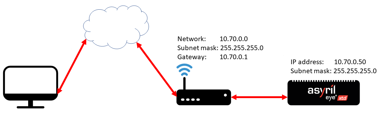
Fig. 33 Indirect connection via the Communication port
Once you have access to EYE+ XTD Studio, go to Communication Configuration to enter your company’s network configuration (e.g. Fig. 34).
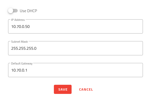
Fig. 34 Enter your company’s network configuration
Important
Once you have changed the Communication port configuration and clicked , you will lose the connection to EYE+ XTD Studio.
You can now reconnect to EYE+ XTD Studio via your company network using the newly configured IP address. To do so, connect the Communication port of EYE+ XTD to your company network using an Ethernet cable and connect the RJ45 port of your computer to your company network with another cable. Change your computer’s IPv4 configuration so that it is on the same network as your company’s network.
Once the configuration is complete, open your web browser and enter the IP address of the Communication port of EYE+ XTD in the address bar (e.g. 10.70.0.50). The interface displayed in Fig. 32 should appear.
Note
If the home page does not have the same display as in Fig. 32, refer to the sections Recommended web browsers and Interface display.
Note
If the home page does not appear, please refer to Connection lost?.
Tip
Indirect connection can also be made using DHCP protocol. The procedure is the same but the DHCP server automatically gives an IP address, subnet mask and gateway to the Communication port of EYE+ XTD. To find out the configuration applied by the DHCP server, you must ask your company’s IT department which IP address has been linked.