Warning
You are reading an old version of this documentation. If you want up-to-date information, please have a look at 1.1 .Communication
Access the communication configuration through and Communication.
From here, you can change the configuration settings of the communication interfaces, namely Fieldbus (in case there is one plugged in), TCP/IP Communication and External. Make sure that your configuration settings are compatible with the configuration of the devices connected to EYE+ XTD. They must be on the same network.
Note
The Ethernet Connections shown on this page will change depending on your EYE+ XTD Controller cover revision.
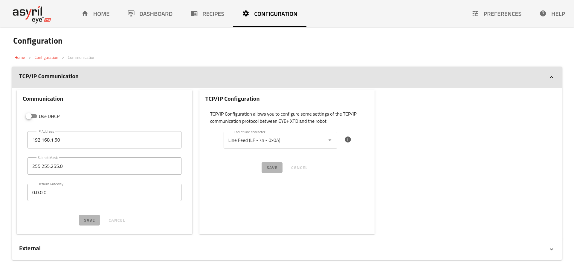
Fig. 132 COMMUNICATION main page
Fieldbus Module Section
The Fieldbus Module section shows information related to the optional Fieldbus Module. This section only appears when a Fieldbus module is plugged in.
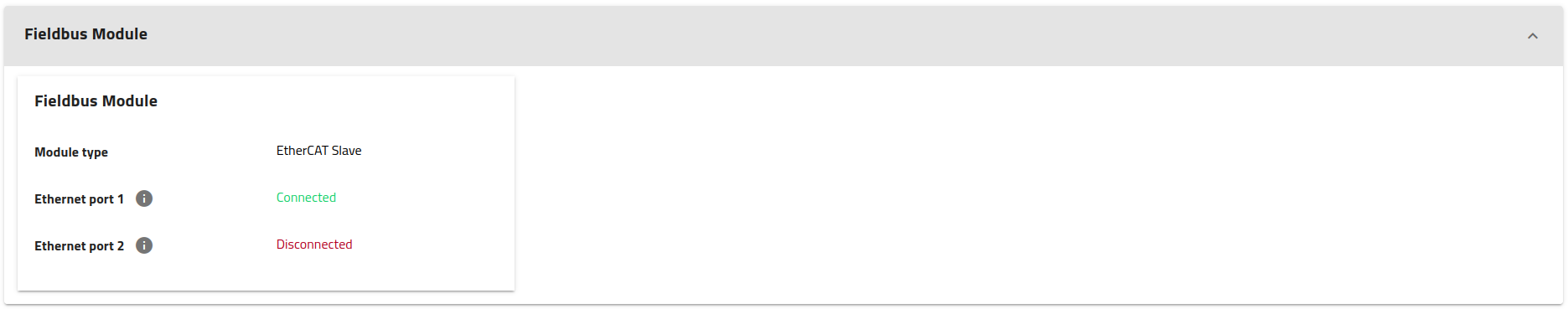
Fig. 133 COMMUNICATION Fieldbus Module section
Module type, type of the module (i.e. the Fieldbus technology supported)
Ethernet port 1, Information related to the Ethernet port 1 (next to LEDs).
Ethernet port 2, Information related to the Ethernet port 2.
Other(s), various other information related to the specific Fieldbus Module installed (see the specific documentation in Fieldbus Integration).
TCP/IP communication
In the TCP/IP communication section, you can change the IP settings of the Ethernet connection used for TCP/IP communication (Communication or Robot depending on your EYE+ XTD Controller cover revision) as well as the TCP/IP configuration.
The available ports for the TCP/IP communication are 7171, 171 and 17171.
Note
EYE+ XTD Controller listens to the three ports simultaneously, we recommend to choose 7171, however depending on your requirements you might choose another one from the list.
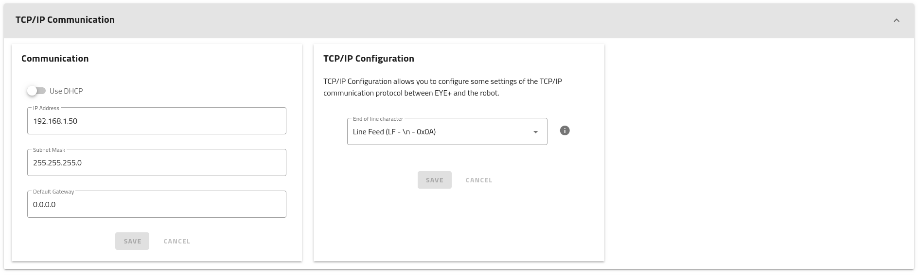
Fig. 134 TCP/IP communication
Communication
The Communication port can be used for two different actions:
Communicate with robot or PLC through TCP/IP Communication.
Access EYE+ XTD Studio to configure devices (camera, robot), create recipes or to visualize the dashboard.
The default settings of the Communication port are presented in General Ethernet Settings.
If the default IP address range is not compatible with your robot/PLC configuration, you can change the IP address and subnet mask of the Communication port of the EYE+ XTD Controller to be on the same network as your robot/PLC.
Important
EYE+ XTD will reject any network overlap while setting the new configuration. This means that it is impossible for example to keep the default IP address and set the mask at 255.255.0.0 as this would overlap with the Camera.
If you want to connect EYE+ XTD to your company network via indirect connection, you need to change the IP address, subnet mask and default gateway of the Communication port of EYE+ XTD to match your company network configuration.
It is also possible to use the DHCP configuration mode. The DHCP server will automatically give an IP address, subnet mask and gateway to the EYE+ XTD Configuration port.
Note
To find out the settings applied by the DHCP server, you must ask your company’s IT department which IP address has been linked.
TCP/IP Configuration
This section allows you to select a different end of line delimiter. This might be required depending on your robot and/or PLC.
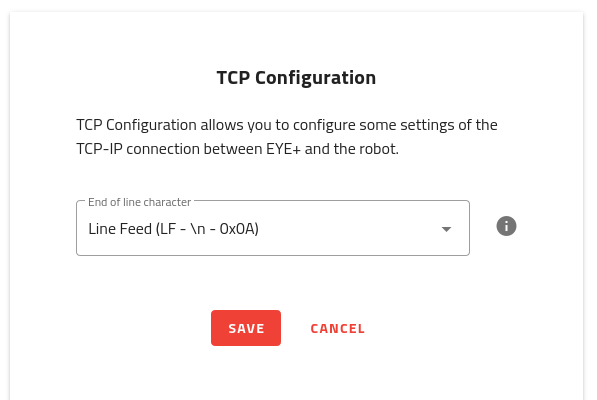
Three different options are available:
LF, end of line delimiter is the special character LF (i.e
\n, ASCII code0x0A)CR + LF end of line delimiter is the special character CR + LF (i.e
\r\n, ASCII codes0x0D 0x0A)CR end of line delimiter is the special character CR (i.e
\r, ASCII code0x0D)
The default end of line delimiter used by EYE+ XTD Controller is LF.
Note
When changing this setting, any open connection will be forcefully terminated.
External
The Network section allows you to modify the External 1 and External 2 ports. The default settings of the External 1 and External 2 ports are presented in General Ethernet Settings.
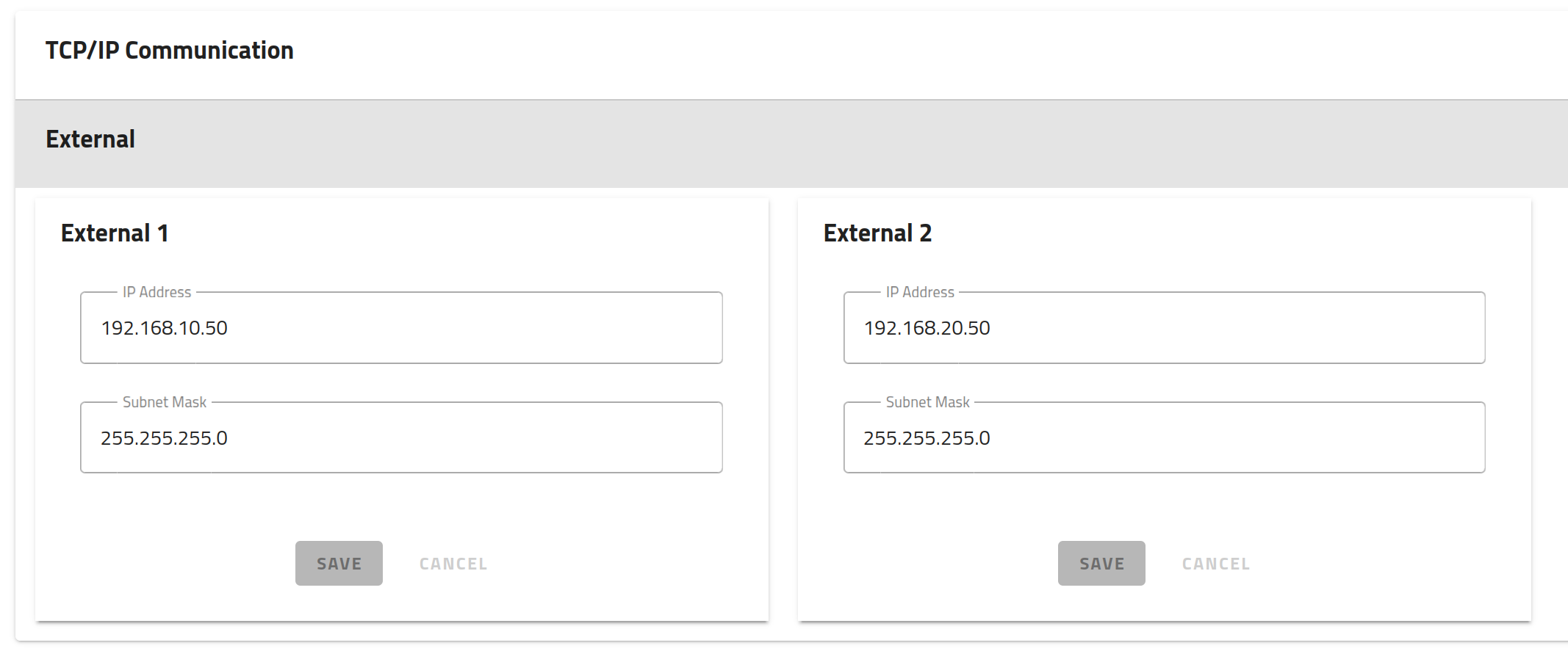
Fig. 135 COMMUNICATION External section
This default configuration means that your computer can only connect via direct connection and the IP address of your computer’s port must be between 192.168.10.1 and 192.168.10.254 or 192.168.20.1 and 192.168.20.254 respectively, depending on what port you are using.
Note
Configuring a gateway for External 1 or External 2 is not supported, use the Communication port instead.
Important
EYE+ XTD will reject any network overlap while setting the new configuration. This means that it is impossible for example to keep the default IP address and set the mask at 255.255.0.0 as this would overlap with the Camera.