Warning
You are reading an old version of this documentation. If you want up-to-date information, please have a look at 1.1 .Hand-eye calibration wizard
This wizard guides you to perform the hand-eye calibration.
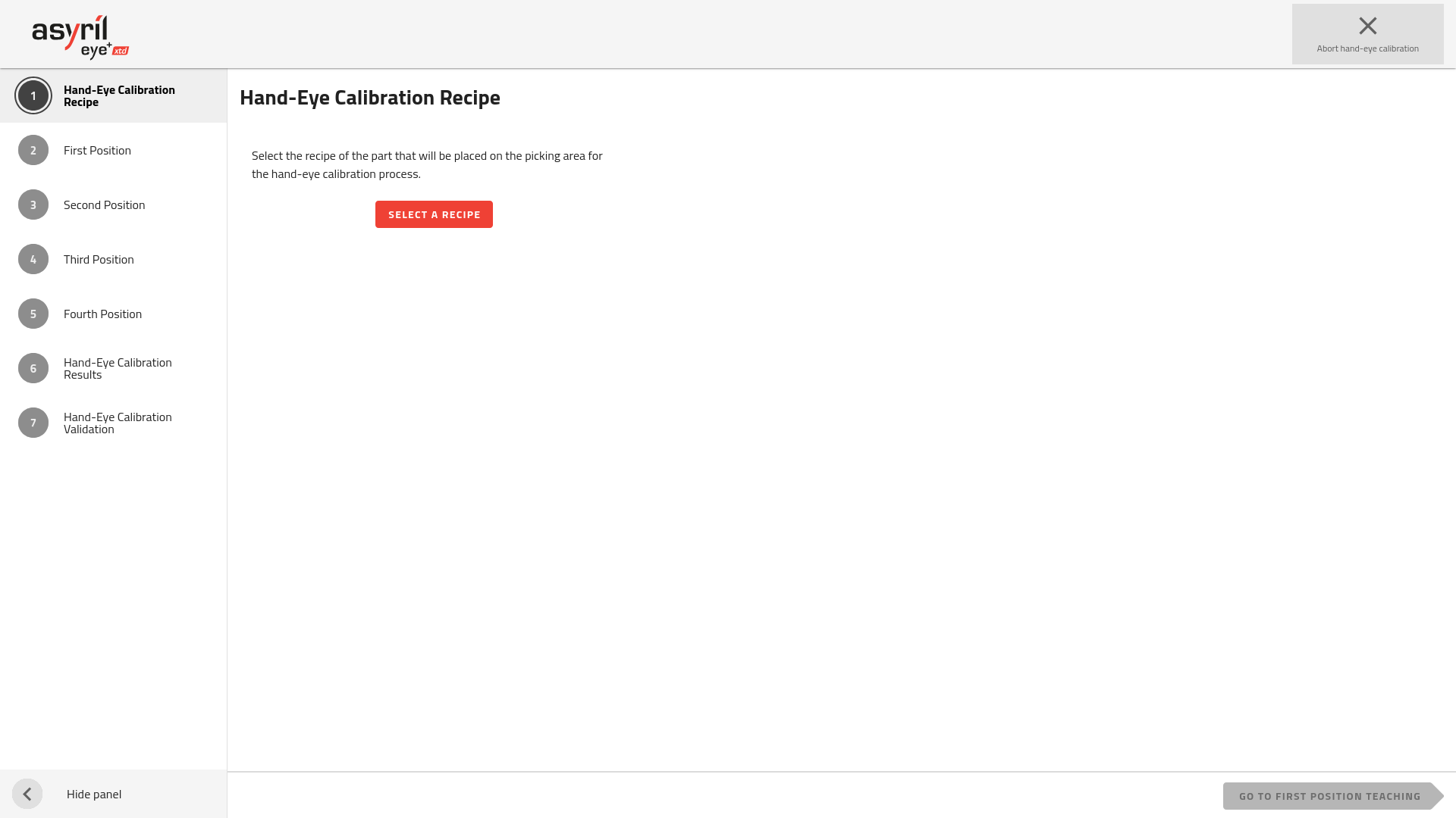
Fig. 158 Hand-Eye Calibration wizard
It is made up of 7 steps.
Note
Refer to section Hand-eye calibration - good practices to have information about how to place the robot frame and how to increase the hand-eye calibration accuracy.
1. Hand-Eye Calibration Recipe
Before starting the hand-eye calibration, you must select a recipe to use as a reference. The necessary parameters from the selected recipe will be copied into a dedicated hand-eye calibration recipe. Note that there is no ongoing link between the original recipe and the hand-eye’s recipe, settings are copied at the time of selection.
Note
If you need to modify the hand-eye calibration recipe, you must modify this recipe in and then start the hand-eye calibration again by selecting the modified recipe.
You can either choose the recipe of the part you want to pick in production or you can choose a specific part that is only used for accurate calibration (refer to section Using a part dedicate for hand-eye calibration).
Important
However in any case you must use the production plate that you will use in the production state. If you do not, the coordinates of the parts could be inaccurate.
Once you have selected the recipe you want to use, the following information is displayed:
Recipe name
Part height
A picture of the chosen part
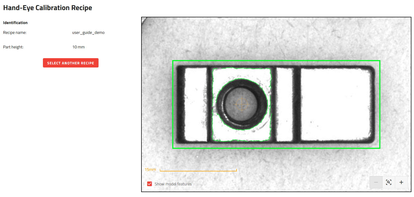
Fig. 159 Hand-Eye Calibration Recipe
2. First Position
This step is made up of 5 sub-steps.
a. Prepare Gripper
There are two possibilities to prepare the gripper:
The first way to do this is to place the part directly into the gripper. Make sure that the part is positioned in the gripper in the same way as it will be positioned in production. Try to place the part as accurately as possible in the gripper. The Tool center point (TCP) must be placed at the picking position you defined in the recipe.
Important
If the part does not have exactly the same position in the gripper for all four positioning steps (2. First Position, 3. Second Position, 4. Third Position, 5. Fourth Position), this will lead to a decrease in the accuracy of your calibration because the picking position detected by the vision will not be perfectly aligned with the coordinates of the robot you will supply.
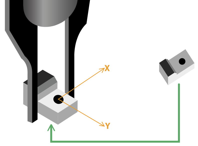
Fig. 160 Prepare the gripper: first way to do
The second way to proceed is to place the part directly on the plate without using the gripper. The part must be oriented in such a way that it can be picked up by the gripper. The advantage is that in the next step, the gripper will not need to touch the part. Since the hand-eye calibration only processes the X and Y positions, the TCP can be placed above the picking position without touching the part.
b. Move Robot
Move the robot to the correct position. Two ways to do this:
Fig. 161 Move the robot to the first position
The first way to do this is to move the gripper (which holds the part) to one of the four corners of the picking area. The part must touch the surface perfectly and must always be well held by the gripper on the picking position.
The second way to proceed is to place the TCP over the part already in place in the picking area. The part must initially be placed in one of any one of the four corners of the picking area.
Note
To increase the accuracy of your calibration, be sure to place each of the four positions as far apart as possible.
c. Robot Coordinates
Fill in the gripper’s robot coordinates. The coordinates must be within the robot coordinate frame you chose ( Robot coordinate frame (RCF)).
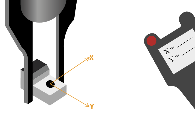
Fig. 162 Fill in the robot coordinates
Note
Fill in the robot coordinates in the measurement unit of your robot. Some robots work in meters/inches, others in millimeters…
d. Remove Robot
Release the part (if needed) and remove the robot from the field of view of the camera.
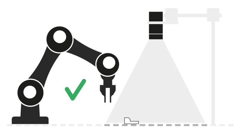
Fig. 163 Remove the robot from the field of view of the camera
Important
Be careful not to move the part when moving the robot out of the field of view. This will result in a decrease in the accuracy of your calibration.
e. Take Picture
Take a picture of the part on the picking area. EYE+ XTD will deduce the coordinates of the part in the vision coordinate frame.
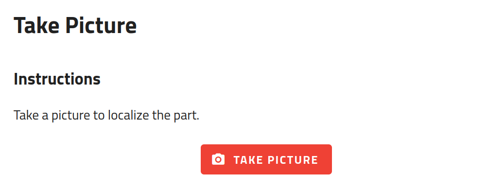
Fig. 164 Take a picture of the part
Note
If EYE+ XTD did not found the part, restart this step and place the part differently. If that still does not work, check your recipe.
3. Second Position
The procedure is the same as presented in section 2. First Position. The part must be placed in a different corner than the first positioning (Fig. 165).
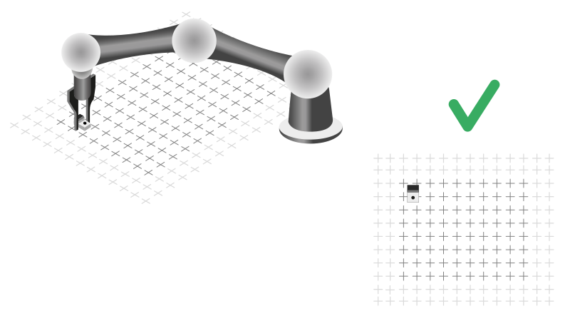
Fig. 165 Move the robot to the second position
4. Third Position
The procedure is the same as presented in section 2. First Position. The part must be placed in a different corner than the first and second positioning (Fig. 166).
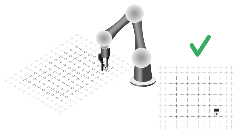
Fig. 166 Move the robot to the third position
5. Fourth Position
The procedure is the same as presented in section 2. First Position. The part must be placed in a different corner than the first, second and third positioning (Fig. 167).
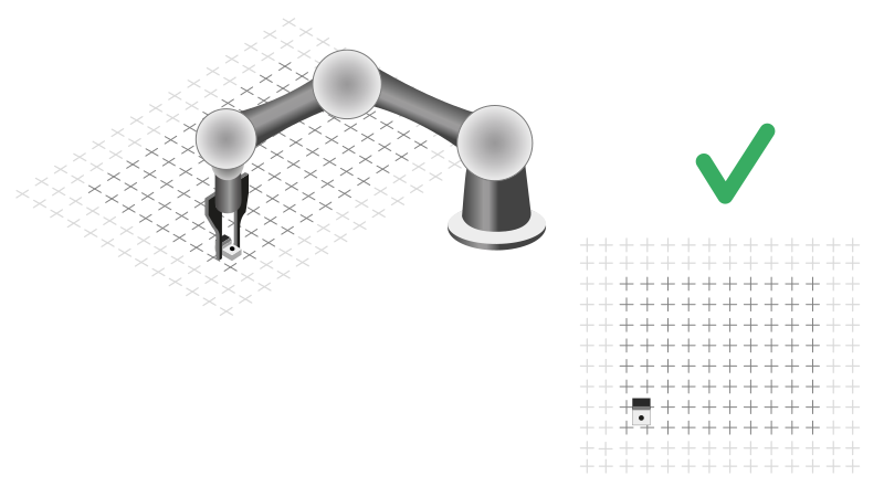
Fig. 167 Move the robot to the fourth position
6. Hand-Eye Calibration Results
You can now see the result of the hand-eye calibration in the displayed table (Fig. 168). This summarizes all the coordinates of the part within the vision and the robot coordinate frames. It also displays the calibration accuracy of your hand-eye calibration.
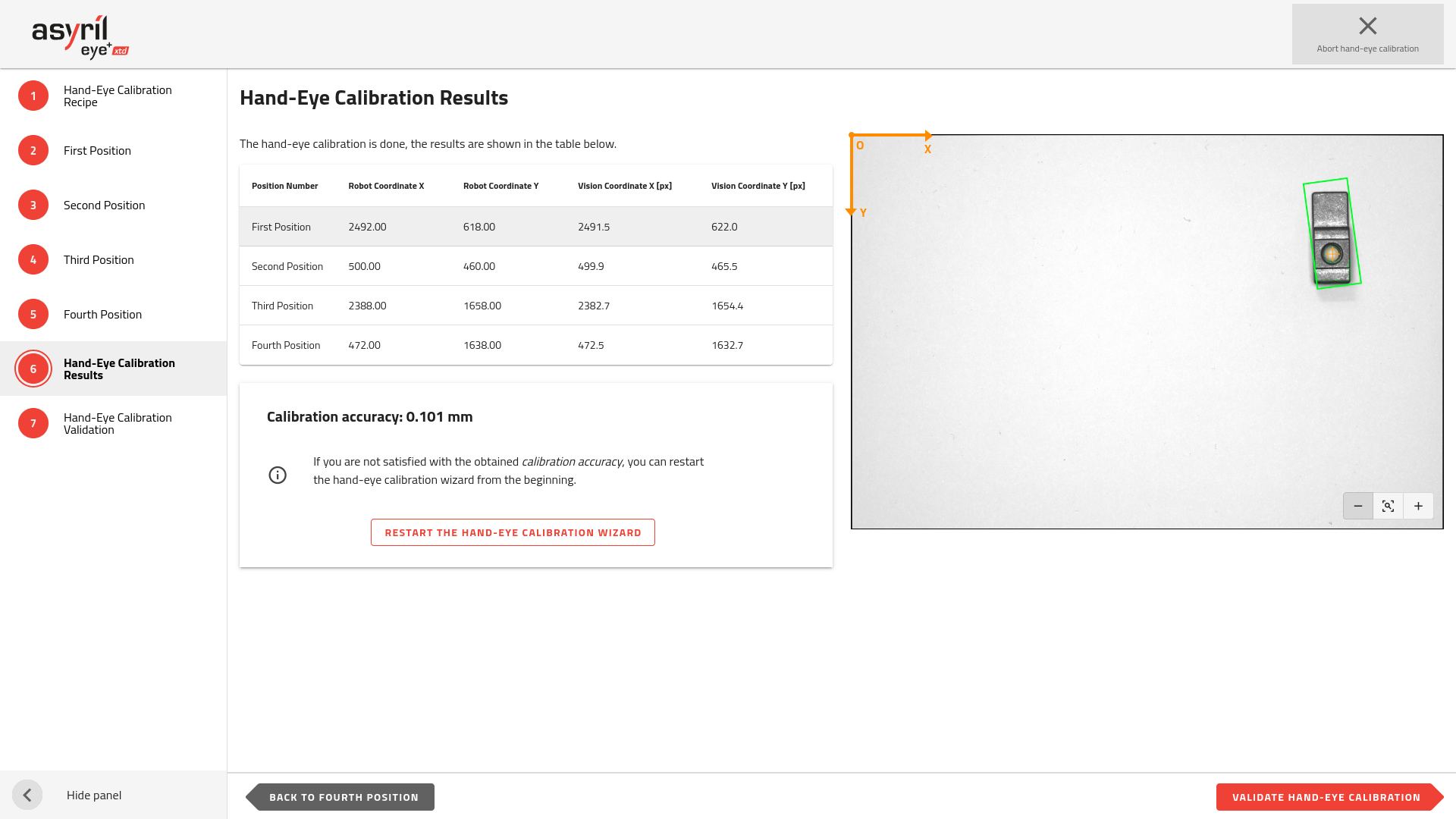
Fig. 168 Hand-eye calibration results
The calibration accuracy will inform you about the quality of the hand-eye calibration. If you are satisfied with this accuracy, you can proceed to the last step which will be a validation step.
If not, we recommend to redo the hand-eye calibration. Consult the section How can I increase hand-eye calibration accuracy? for tips to increase the accuracy.
7. Hand-Eye Calibration Validation
This step allows you to validate the hand-eye calibration by doing a manual pick and place.
Place a part somewhere on the plate, for example near the middle, and click on . The coordinates displayed in the table are corresponding to the robot coordinate frame.
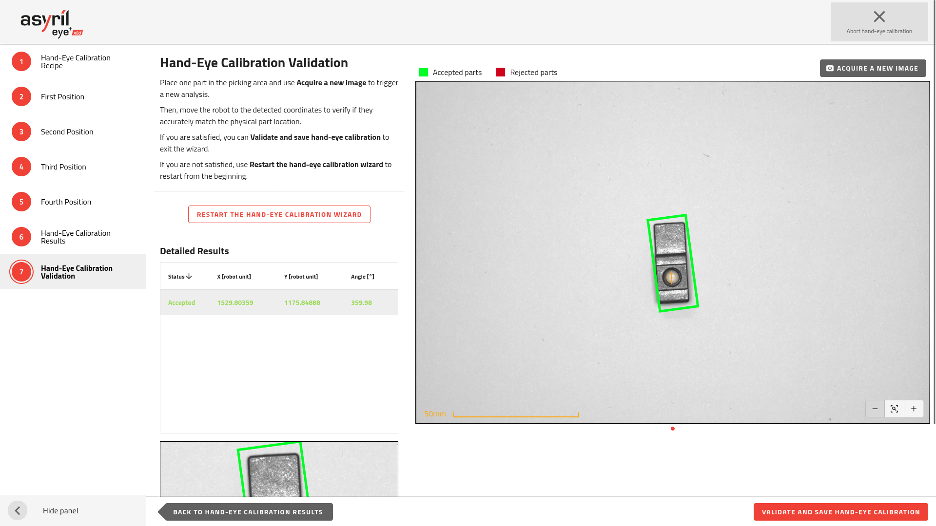
Fig. 169 Hand-eye calibration validation with one part detected
Then, move the robot to the defined coordinates and validate that you can pick the part. If that is fine, you can exit the wizard by clicking on .
If not, we recommend to redo the hand-eye calibration. Consult the section How can I increase hand-eye calibration accuracy? for tips to increase the accuracy.
Note
The validation step is optional but we advise you to do it in order to verify that the hand-eye calibration was done properly.
Note
For more information about hand-eye calibration, refer to the section What is hand-eye calibration?.
The coordinates sent by EYE+ XTD will now be automatically converted and transmitted in the Robot’s coordinate frame.
Important
EYE+ XTD also transforms the RZ angle into the Robot Coordinate Frame. EYE+ XTD computes an offset angle between the vision’s X-axis and the robot Robot Coordinate Frame’s X-axis, this offset is then applied before coordinates are sent.