Warning
You are reading an old version of this documentation. If you want up-to-date information, please have a look at 1.1 .Camera configuration wizard
This wizard guides you to finalize the vision system installation and to perform the vision calibration.
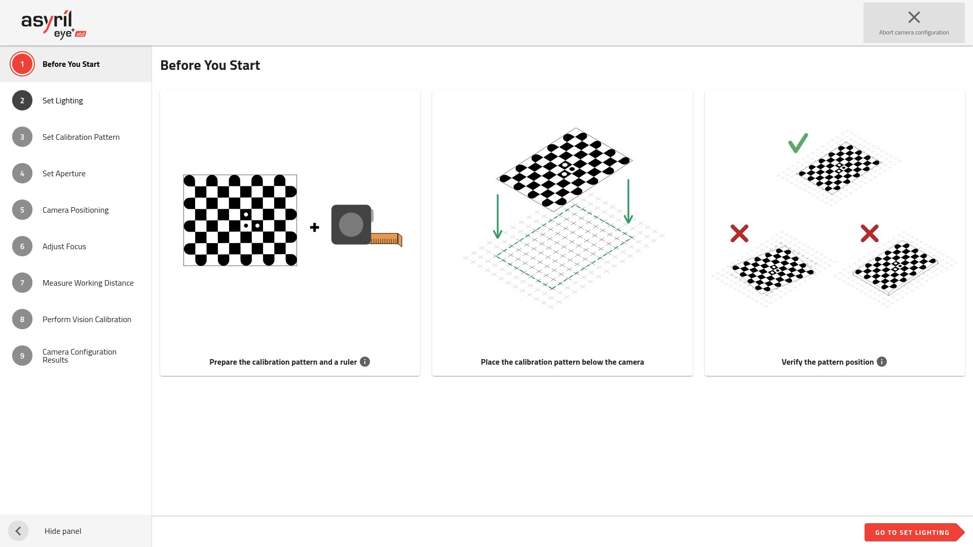
Fig. 136 Camera configuration wizard
The camera configuration wizard consists of 9 steps.
Before starting this wizard, ensure the camera is correctly installed:
Camera is placed above the center of the picking area.
Distance between the front face of the lens and the picking area plate corresponds to your EYE+ XTD kit working distance.
The camera EYE+ XTD logo is oriented along the longest side of the picking area.
The lens cover is removed.
Note
Refer to section Mounting the camera and the lens to get more information.
1. Before you start
Prepare a ruler (in meters or inches).
Important
Keep the same installation it would be in production state. For example if in production state something obstructs the view of the camera, you must leave this element as it will allow to define the region of interest in your installation during the camera configuration.
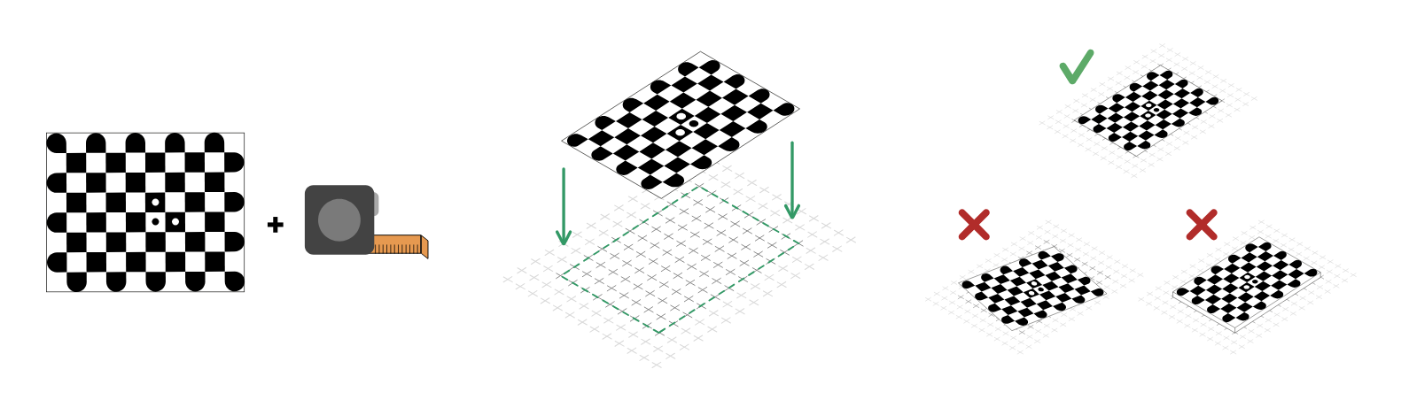
Fig. 137 Before you start
2. Set lighting
You have to choose the available lighting you want to use when configuring the camera. You can turn on and off the backlight and frontlight, but you have to select at least one.
Tip
We advise you to provide all available lighting. This will also correspond to the lighting available when creating a recipe later. For the calibration, the system will automatically choose the most appropriate lighting.
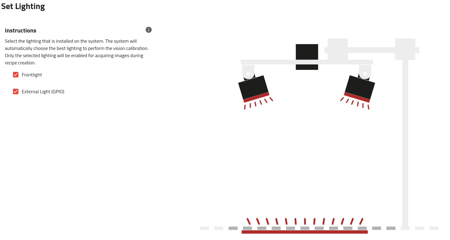
Fig. 138 Set lighting
3. Set the calibration pattern
This step allows you to enter the necessary settings for your custom calibration pattern. For guidance on creating a pattern, refer to the chapter: How to create a pattern for the camera configuration.
If you are using an Asyril standard calibration platform, you can simply import the configuration by clicking on .
The following parameters are required to perform the calibration:
Number of Squares: Total number of squares in the pattern, including ones that have round corners.
Square Size: The physical length of one side of a single square (in millimeters or inches).
Support Thickness: The thickness of the material on which the pattern is printed or mounted.
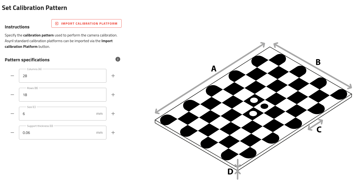
Fig. 139 Set the calibration pattern
4. Set aperture
Adjust the camera aperture to 5.6. This aperture is well adapted to the camera and lens provided in the EYE+ XTD kit to achieve optimal contrast in the images. Then you can lock this aperture value using the top screw of the lens.
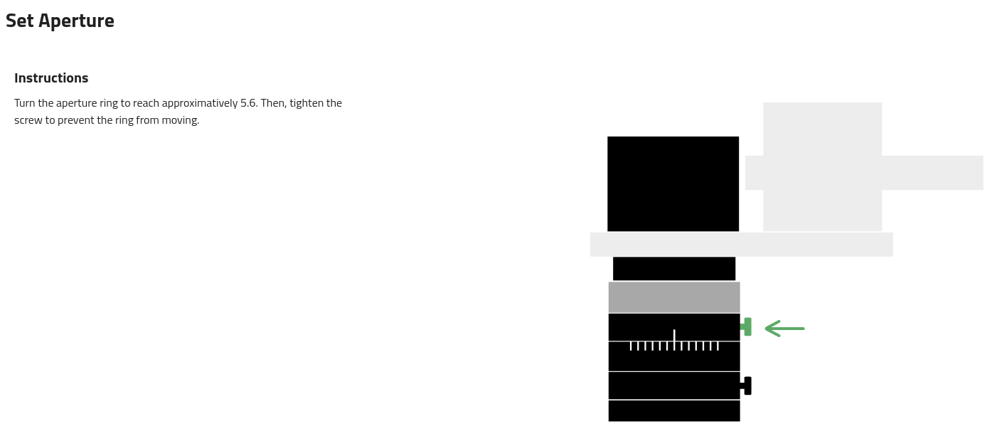
Fig. 140 Set aperture
5. Camera Positioning
Check here if your vision system is properly mounted. If it is not, you will need to adjust your installation properly.
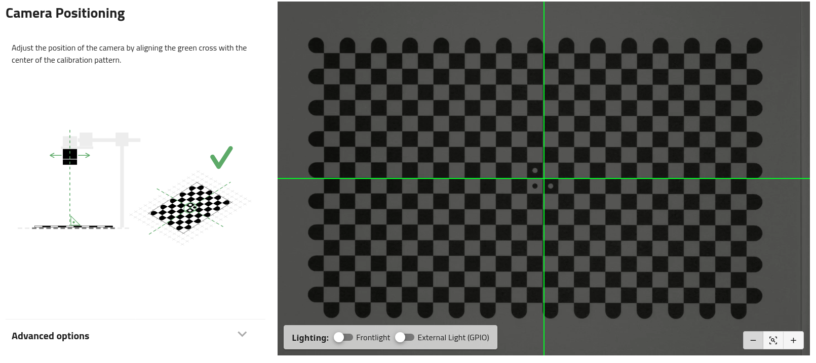
Fig. 141 Center position
Tip
If the calibration plate is not correctly visible (too dark), turn on the backlight.
You must adjust the position of the camera until the center of the green cross is roughly in the center of the vision calibration plate. Once this is done, the camera can be rigidly fixed. Never move the camera after this.
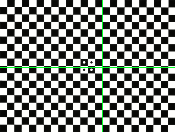
Fig. 142 Not well centered
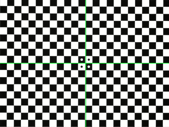
Fig. 143 Well centered
To help you adjust the center position more precisely, you can use the Zoom feature. To zoom, use the + Button located at the bottom right corner of the live view.
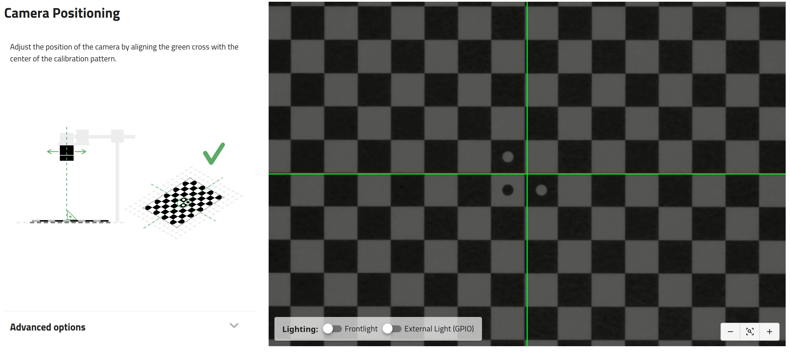
Fig. 144 Center position zoomed-in
Note
The camera configuration is robust enough so that the edges of the calibration plate can be partially occluded. Up to one line can be occluded on the long axis and up to 3 lines on the short axis.
However, if too many lines are occluded, the system will display a generic error message: “Unable to perform vision calibration”.
6. Adjust focus
Adjust the focus until the image appears as sharp as possible. Once optimal focus is achieved, secure the position by tightening the bottom screw on the lens. You can use the focus gauge displayed on the left side of the live view to fine-tune the focus.
If you are using polarized lighting, make sure to mount the polarization filter correctly. Rotate it to minimize reflections, then tighten the locking screw to prevent the filter ring from shifting.
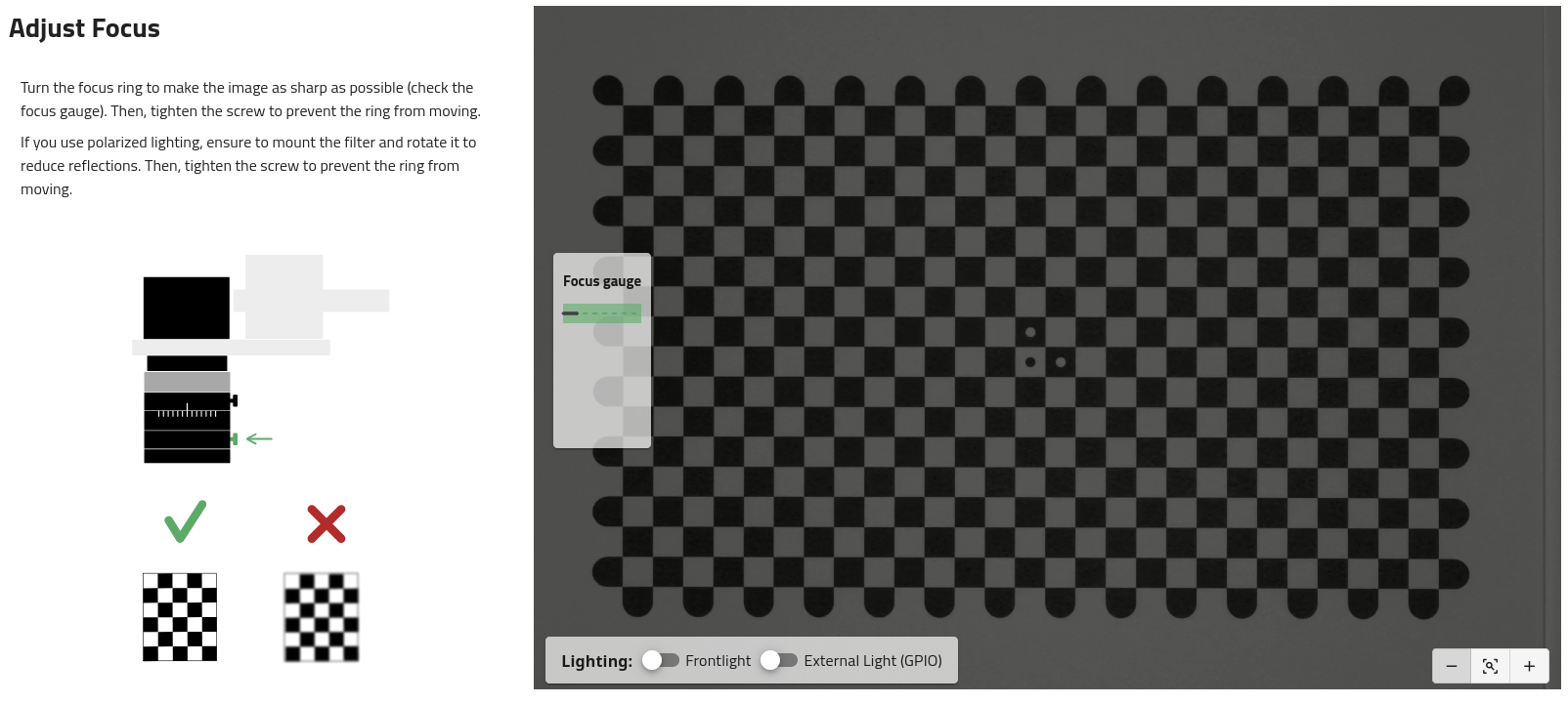
Fig. 145 Adjust focus
Important
If you do not perform this step correctly, you may reduce the performance of image analysis.
Tip
If the calibration plate is not correctly visible (too dark), turn on the backlight.
7. Measure working distance
Measure the distance from the calibration plate to front face of the lens. This working distance is required in order to correct the parallax effect on your parts. Enter this measurement value in the interface.
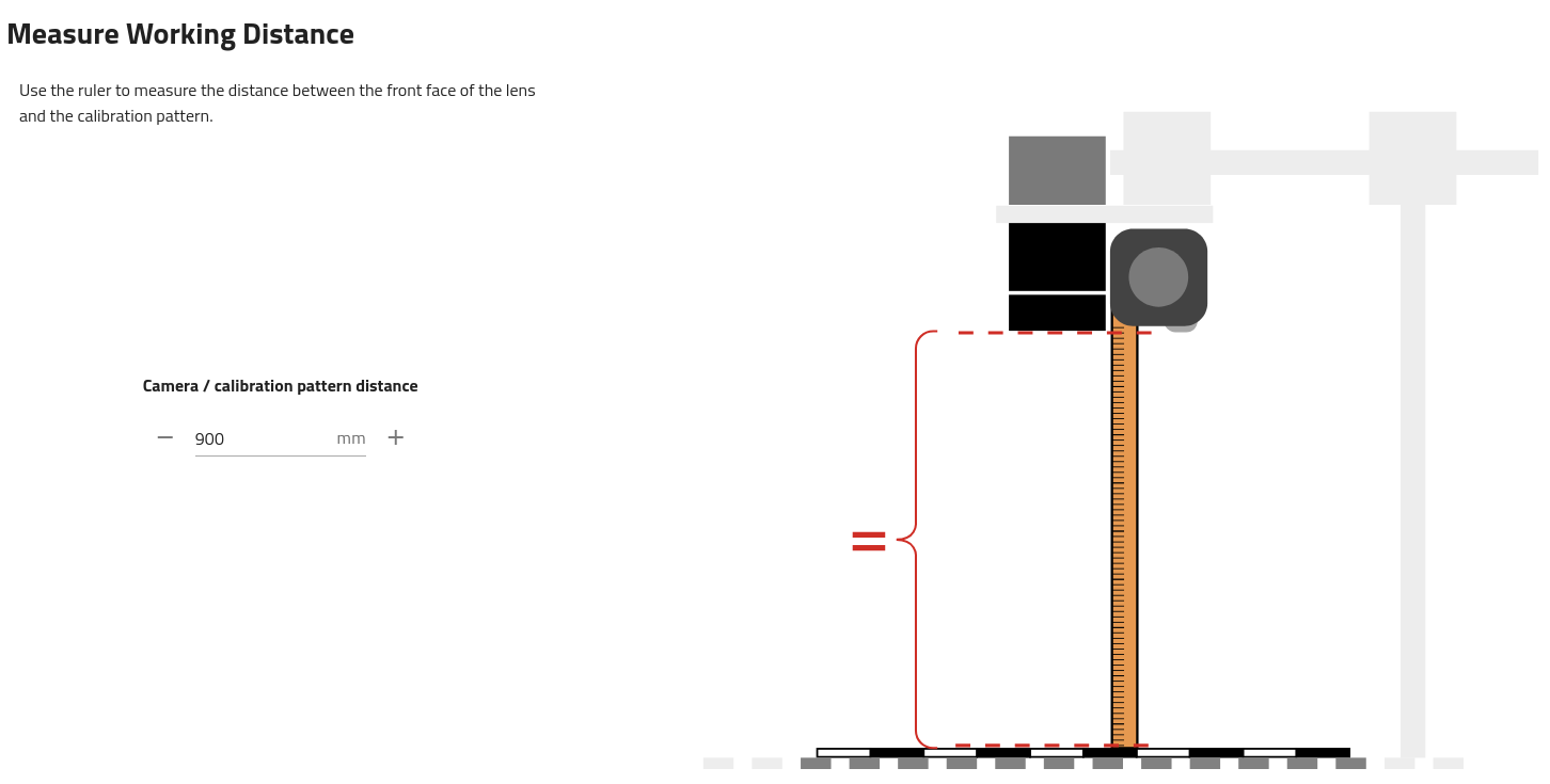
Fig. 146 Measure the working distance
Note
For more information about what parallax effect is and how it is corrected, refer to the section Perspective projection correction.
8. Perform vision calibration
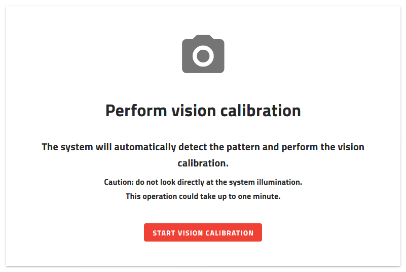
Fig. 147 Perform vision calibration
Make sure that the field of view of the plate is clear and then click .
This step starts the vision calibration. It will take into account the parameters previously input. Vision calibration applies corrections to the image using the checkerboard printed on the calibration pattern. The vision calibration performs:
Distortion correction
RMS error of the distortion correction calculation
Region of interest (ROI) definition
Pixel-millimeter or pixel-inch scale calculation
Parallax correction
Note
Refer to section What performs vision calibration? to have more information about the vision corrections.
9. Camera configuration results
On the camera configuration results, you can see one image before and one image after vision calibration (Fig. 148).
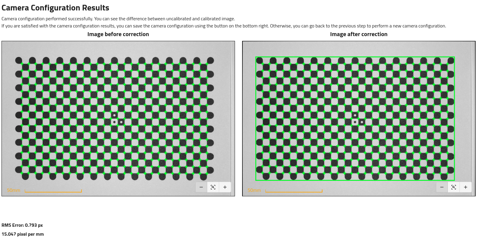
Fig. 148 Camera configuration result
Note
The before/after image presented might be very similar as the lenses we have selected for the vision kit have a very little fish-eye effect.
The green rectangle on the right image represents the region of interest.
The RMS error and the pixel-millimeter or pixel-inch scale are displayed here.
Important
If the RMS error is greater than 1, the correction is not applicable.
If you are satisfied with the results, you can click on the to save and close the wizard.