Warning
You are reading an old version of this documentation. If you want up-to-date information, please have a look at 1.1 .2.3 Results
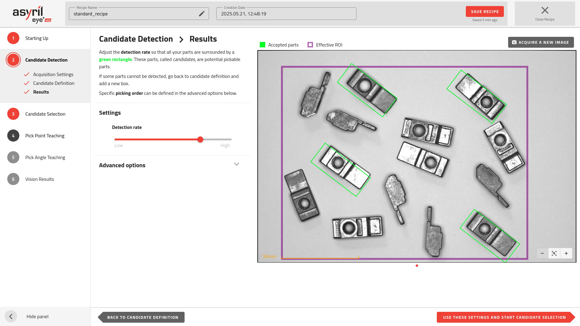
Fig. 64 Candidate Detection - Results
The Results page displays the outcome of the candidate detection algorithm applied to the candidates defined in the previous step. Detected parts are marked with green rectangles and are referred to as candidates, representing potential pickable parts.
If some parts are not detected, try increasing the detection rate first. If this does not solve the issue or if undesired elements are detected, return to 2.2 Candidate Definition and add an additional candidate detection box.
Important
If a part is not surrounded by a green rectangle at the end of this step, it will be discarded for all the following steps, meaning that it will not be picked by the robot if its position does not change.
Tip
You can manually move the parts and then hit to analyze a new image and check whether the candidate detection is performing well.
Note
The results image shows the Region of Interest (ROI) as a purple rectangle. Make sure that this fully encompasses your picking area.
Advanced options
Picking order
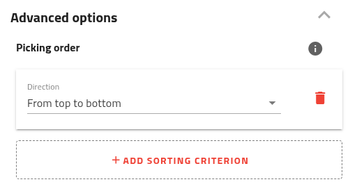
Fig. 65 Picking order configuration with one direction already set
The picking order defines the sequence in which coordinates are returned by EYE+ XTD during production. It enables you to optimize the robot’s path or execute advanced scenarios where the picking area needs to be cleared in a specific way.
You can configure up to two sorting criteria, allowing you to specify either a general direction or a grid-based order. The available sorting options are:
From top to bottom
From bottom to top
From left to right
From right to left
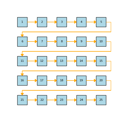
Fig. 66 Example of a picking order defined as: 1. From left to right 2. From top to bottom
Once at least one criterion is selected, the picking order will be displayed on the results image (Fig. 67).
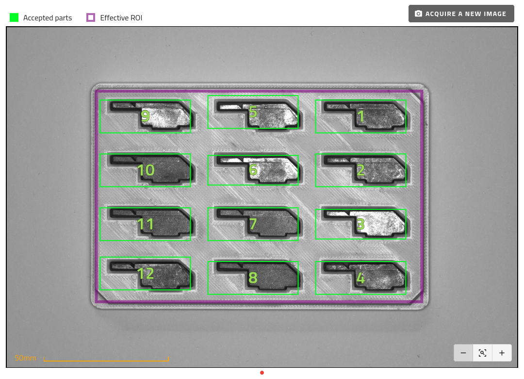
Fig. 67 Results with picking order displayed: 1. From top to bottom 2. From right to left
Note
If no picking order is defined, parts are automatically sorted by their distance to the center of the picking area, with the closest parts picked first.